Generate
Create images with AI
Braking System Blueprint Infographic
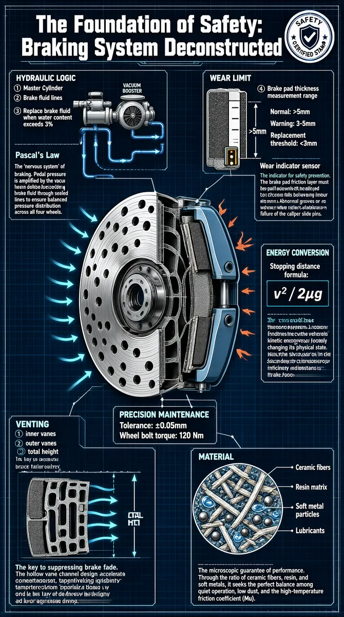
This infographic is presented in an engineering blueprint style, with a deep blue grid background and white lines outlining the various components of a car's braking system and how they work. The overall layout adopts a hub-and-spoke structure centered on the brake disc and caliper, while multiple sub-diagrams and annotation areas explain key components and technical parameters in detail. The title sits at the top center in bold, eye-catching lettering: "The Foundation of Safety: Braking System Deconstructed", with a circular "SAFETY CERTIFIED STAMP" seal on the right, underscoring the professionalism and safety of the content. --- **Main Diagram Structure and Section Details:** 1. **(Hydraulic Logic)** - Located in the upper left, showing a schematic of the brake fluid line system. - Label ①: Master Cylinder, connected to the vacuum booster. - Label ②: Brake fluid lines, with arrows indicating the direction of fluid flow. - Label ③: Brake fluid must be replaced when water content exceeds 3%. - Text: "The 'nervous system' of braking. Pedal pressure is amplified by the vacuum booster, driving brake fluid through sealed lines to ensure balanced pressure distribution across all four wheels." - Introduces "Pascal's Law" as the theoretical foundation. 2. **(Wear Limit)** - Located in the upper right, showing a cross-section of a brake pad. - Label ④: Brake pad thickness measurement range. - Normal: >5mm - Warning: 3-5mm - Replacement threshold: <3mm - The diagram is labeled "Wear indicator sensor". - Text: "The indicator for safety prevention. The brake pad friction layer must be replaced when its thickness falls below 2-3mm. Abnormal grooves or uneven wear reflect lubrication failure of the caliper slide pins." 3. **(Energy Conversion)** - Located center-right, around the brake disc and caliper assembly. - Text: "The core logic of the braking system. Friction converts the vehicle's kinetic energy into heat, forcibly changing its physical state. The core of the design lies in heat dissipation efficiency and resistance to brake fade." - Labeled nearby: "Stopping distance formula: v² / 2μg". 4. **(Venting)** - Located in the lower left, showing the cross-section of a ventilated brake disc. - Label ①: inner vanes; Label ②: outer vanes; Label ④: total height. - Arrows indicate air convection paths. - Text: "The key to suppressing brake fade. The hollow vane channel design accelerates air convection, preventing high temperatures from vaporizing brake fluid. It is the last line of defense for braking power under aggressive driving." 5. **(Material)** - Located in the lower right, showing the microstructure of brake pad materials. - The diagram breaks down into four parts: - Ceramic fibers - Resin matrix - Soft metal particles - Lubricants - Text: "The microscopic guarantee of performance. Through the ratio of ceramic fibers, resin, and soft metals, it seeks the perfect balance among quiet operation, low dust, and the high-temperature friction coefficient (Mu)." 6. **(Precision Maintenance)** - Located center-lower, around the brake disc. - Labeled "Tolerance: ±0.05mm", emphasizing manufacturing precision. - Labeled "Wheel bolt torque: 120 Nm", noting installation specifications. 7. **(Core Component Illustration)** - The central body is a perspective cutaway of the brake disc and caliper assembly. - The brake disc features vented hole design, with the caliper clamping from both sides. - Multiple arrows surround the brake disc, illustrating heat dissipation paths and airflow. --- **Visual Elements and Data Encoding Methods:** - Standard engineering drawing symbols are used: dashed lines for internal structures, solid lines for outer contours, and arrows for direction. - All dimensions, values, and tolerances are annotated with precise figures, such as "120 Nm", "±0.05mm", ">3%", "v²/2μg", etc. - Color coding: mainly white lines on a blue background; key terms such as "Pascal's Law", "Precision Maintenance", and "Energy Conversion" are highlighted in light cyan for readability. - Text typography is clear, with titles and body text layered; technical terms are given in both Chinese and English (e.g., "Wear indicator sensor", "Venting", "Material"). - The layout is clearly hierarchical, moving progressively from the macro system to micro materials, with coherent logic. --- **Summary:** This infographic systematically dissects the safety architecture of a car's braking system, covering five major dimensions: hydraulic transmission, energy conversion, materials science, heat dissipation design, and maintenance standards. Through the engineering blueprint format, combining precise technical parameters with intuitive structural diagrams, it fully reveals how modern braking systems safeguard driving safety under extreme operating conditions. All text is in English, consistent with the task's primary-language determination.
Tags
More Images